Reactance, impedance and phasor diagrams
Key ideas
- In AC, capacitors and inductors oppose current without dissipating energy. This frequency-dependent opposition is reactance (unit: ohms):
- Capacitive reactance — falls as frequency rises (more frequent recharging = more current):
- Inductive reactance — rises with frequency (faster current changes = more back-EMF):
- Phase: in a resistor, voltage and current rise and fall together. In L and C they are a quarter-cycle (90°) apart:
- inductor — voltage leads the current by 90°
- capacitor — voltage lags the current by 90°
- (memory aid: CIVIL — in a C, I leads V; V leads I in an L)
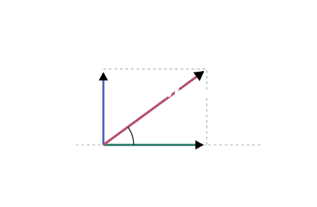
- A phasor diagram draws each voltage as an arrow rotating at ; lengths are the peak (or rms) values, angles are the phases. In a series circuit every component shares the same current, so the current phasor is the reference:
- along the current
- at 90° ahead; at 90° behind
- the supply voltage is the vector sum
- Because and (or ) are perpendicular, the sum uses Pythagoras — voltages in AC series circuits don't simply add.
- Impedance is the circuit's total opposition, defined through . For a series LR circuit: (and likewise with for CR).
A H inductor in series with a Ω resistor is connected to a V rms, Hz supply. Find the impedance and the rms current.
Step 1 — Inductive reactance at 50 Hz
Step 2 — Impedance (perpendicular phasors → Pythagoras)
Step 3 — Current from
Tips
- Frequency dependence is the favourite explain question: high frequency → inductor dominates (), capacitor fades (); low frequency → the reverse. A capacitor blocks DC entirely ( at ).
- In a series circuit, always take the current as the phasor reference — every component shares it. Trying to reference the supply voltage first makes the diagram unbuildable.
Test yourself
Practice by grade
One question each at Achieved, Merit and Excellence. Have a go, then compare with the model answer.
Achieved
A µF capacitor is connected to a Hz supply.
Show that its reactance is about Ω.
Merit
A series CR circuit has Ω and Ω.
Calculate the impedance, and the rms current when the supply is V rms.
Excellence
A student measures the rms voltages in a series LR circuit: V and V, but the supply reads V — not V.
Explain the discrepancy using a phasor diagram, and find the phase angle between the supply voltage and the current.