Resonance in LCR circuits
Key ideas
- In a series LCR circuit, the inductor and capacitor voltages are 180° apart (one leads the current by 90°, the other lags), so their phasors directly oppose.
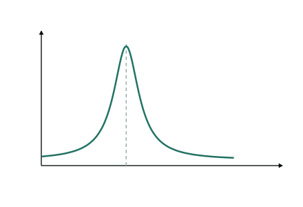
- As frequency rises, grows while shrinks. At one special frequency they are equal — and cancel completely:
- At this resonant frequency:
- the impedance is at its minimum — just
- the current is at its maximum —
- the supply voltage and current are in phase
- large (equal and opposite) voltages can exist across L and C individually, even bigger than the supply — they cancel each other, not the physics.
- Off resonance the circuit is reactive again: below the capacitor dominates (); above, the inductor dominates.
- Application: a radio tuner is an LCR circuit — adjusting moves so only the station at that frequency drives a large current.
A series circuit has H and µF. Find the resonant frequency, and the rms current at resonance when the supply is V rms and Ω.
Step 1 — Resonant frequency
Step 2 — At resonance the reactances cancel, so
Tips
- To raise , make or smaller () — check your answer moves the right way before boxing it.
- Explain resonance in terms of phasor cancellation ( and opposite, equal at ) — "the reactances cancel" plus the phasor reason is what earns Excellence.
Test yourself
Practice by grade
One question each at Achieved, Merit and Excellence. Have a go, then compare with the model answer.
Achieved
A series LCR circuit has H and µF.
Show that its resonant frequency is about Hz.
Merit
A series LCR circuit with Ω is driven at its resonant frequency by a V rms supply.
Calculate the current, and state the phase relationship between the supply voltage and the current.
Excellence
Explain why the current in a series LCR circuit peaks at the resonant frequency, referring to the phasors of the inductor and capacitor voltages and the frequency dependence of the two reactances.