Precedence tables and network diagrams
The precedence table
- A precedence table lists every activity in the project with:
- a label (A, B, C…)
- a description of the task
- a duration, in consistent units
- its immediate predecessors — the activities that must be completely finished before it can start
| Activity | Description | Duration (days) | Immediate predecessors |
|---|---|---|---|
| A | Design and consent | 3 | — |
| B | Order materials | 5 | A |
| C | Clear the site | 4 | A |
| D | Foundations | 6 | C |
| E | Materials delivered | 2 | B |
| F | Build the frame | 7 | D, E |
| G | Lay the decking | 5 | F |
| H | Fit the handrails | 3 | F |
| J | Final inspection | 1 | G, H |
- "Immediate" matters. If C follows A and D follows C, then D's immediate predecessor is C alone — writing "A, C" is redundant and clutters the network.
- An activity with no predecessors starts the project. There may be several.
- An activity that is nobody's predecessor ends the project. There may be several of these too.
- Check the table before drawing. Every activity must appear in the first column, and every letter in the predecessor column must exist as an activity.
The activity-on-arc convention
- Each activity is an ARC — an arrow — labelled with its letter and duration.
- Each NODE is an event: a moment in time when a set of activities is complete and others may begin.
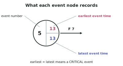
- Nodes are numbered, and each is drawn as a circle divided into three parts:
- the event number
- the earliest event time (from the forward pass)
- the latest event time (from the backward pass)
- The alternative convention, activity-on-node, puts each activity in a box and uses arrows only to show dependency. Project-management software uses it, but the NCEA standard refers to critical events, which exist only in the activity-on-arc convention used here.
Rules for drawing the network
- One start node and one finish node. If several activities have no predecessors, they all leave the start node; if several end the project, they all arrive at the finish node.
- Time flows left to right. Arrows never point backwards.
- An activity can only start when EVERY activity arriving at its tail node is complete.
- No two activities may share both their start and end nodes. If they do, a dummy is needed (below).
- No loops. An activity cannot depend, directly or indirectly, on itself — that would be a project that can never start.
- Keep arcs straight and avoid crossings where you can. Redraw rather than tangle: the diagram is read by the person marking it.
Dummy activities
- A dummy is a zero-duration arc, drawn dashed. It carries a dependency without representing any work.
- Two situations require one:
- Shared dependencies that are not identical. If C depends on A only, and D depends on A and B, a dummy runs from the end of B to the start of C's node — or equivalently from A's node into D's tail node.
- Two activities with the same start and end nodes. Without a dummy they cannot be told apart in the network's notation.
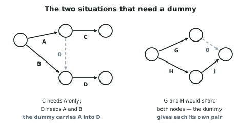
- A dummy takes zero time, so it never lengthens a path — but it does transmit a dependency, and it can be part of the critical path.
- Use as few dummies as possible. Each one adds a node and a chance for error.
Numbering the nodes
- Number so that every arc runs from a smaller number to a larger one. The start node is 1.
- A node cannot be numbered until every activity arriving at it has its tail node numbered.
- This ordering is what makes the forward pass work, because it guarantees you never need a value you have not calculated yet.
Checking the network against the table
- Go back through the precedence table row by row and confirm each activity's tail node has exactly the right predecessors arriving at it.
- The two commonest errors:
- A missing dependency — an activity drawn starting too early, which makes the project look shorter than it is.
- An invented dependency — an activity forced to wait for something the table does not require, which makes it look longer.
- Both errors produce a plausible-looking diagram and a wrong answer, so the check is worth the two minutes.
Worked ExampleBuilding the network for a deck project
Draw the network for the deck project in the precedence table above, numbering the nodes correctly, and verify the diagram against the table.
Step 1 — Identify the start and finish activities
No predecessors: only A, so the project starts with A alone.
Not a predecessor of anything: only J, so the project ends with J alone.
Step 2 — Work out the structure from the table
- A leaves the start node.
- B and C both follow A, so they both leave the node at A's head. The project branches here.
- E follows B; D follows C. Two parallel chains.
- F follows both D and E, so the two chains merge at F's tail node.
- G and H both follow F — branching again.
- J follows both G and H — merging again.
Step 3 — Check whether any dummy is needed
Test the two conditions:
- Do any two activities have exactly the same start and end nodes? No — G and H both start at F's head node but finish at different places… check that. G ends at the node where J starts; H also ends where J starts.
Resolving it: give H its own end node, then run a dashed dummy of duration 0 from that node into J's tail node. H's dependency reaches J unchanged, and the two activities now have distinct node pairs.
Do B and C need one? They share a start node but end at different nodes (E's tail and D's tail) — no dummy needed ✓
Step 4 — Number the nodes
| Node | Meaning |
|---|---|
| 1 | Project start |
| 2 | A complete — B and C may start |
| 3 | B complete — E may start |
| 4 | C complete — D may start |
| 5 | D and E complete — F may start |
| 6 | F complete — G and H may start |
| 7 | H complete (dummy runs 7 → 8) |
| 8 | G complete and dummy arrived — J may start |
| 9 | J complete — project finished |
Check the numbering rule: every arc runs from a lower number to a higher one — , , , , , , , , , ✓
Step 5 — Draw the network
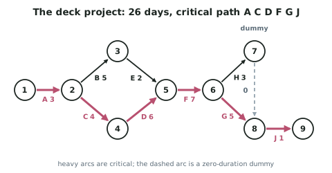
Step 6 — Verify every row of the precedence table
| Activity | Table says it needs | Network shows it starting at | Arriving there |
|---|---|---|---|
| A | — | node 1 (start) | nothing ✓ |
| B | A | node 2 | A ✓ |
| C | A | node 2 | A ✓ |
| D | C | node 4 | C ✓ |
| E | B | node 3 | B ✓ |
| F | D, E | node 5 | D and E ✓ |
| G | F | node 6 | F ✓ |
| H | F | node 6 | F ✓ |
| J | G, H | node 8 | G, and H via the dummy ✓ |
Every dependency in the table appears in the network, and no extra ones have been introduced.
Step 7 — Note what the structure already tells you
The network contains two parallel chains between nodes 2 and 5:
- B then E: days
- C then D: days